- Where to begin?
- How to find a short circuit in the rotor
- disassembly Procedure, repairs, perforator rotor assembly
- Stage I
- Stage II
- Stage III
- As the wind rotor with your hands.
- Variant I
- Variant II
- Booking Process rotor shell
- The impregnation process rotor coils
- The process of stripping surplus reservoir of impregnation
- The process of balancing armature
If you have defined, that broke down the rotor in your punch, and funds for the new you do not have, or have the desire to resurrect the piece with his own hands, then this guide is for you.
Makita rotary hammer device is so simple, that repairs Makita 2450, 2470 It does not cause too much difficulty. the main thing, adhere to our advice.
by the way, Repair punch with your hands can perform virtually every user, having basic skills technician.
Where to begin?
Since the device is simple perforator, the perforator makita repair should start with disassembling. Disassembly of the gun is best done on the already proven order.
Algorithm disassembly punch:
- Remove the rear cover on the handle.
- Remove electrical carbon brushes.
- Disconnecting the mechanical block body and the stator housing.
- From a mechanical disconnect unit rotor.
- Of the stator housing remove the stator.
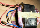
Remember, Green stator housing, the mechanical block body with the rotor black.
Disconnecting the rotor from the mechanical block, proceed to define the nature of the fault. Rotor Makita HR2450 poz.54; article 515668-4.
How to find a short circuit in the rotor
As you produce independent repair hammers, you need
circuitry perforator Makita 2450, 2470.
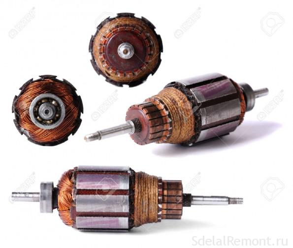
The perforator Makita 2470, 2450 applied collector AC motor.
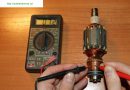
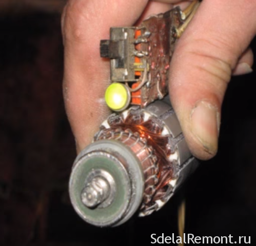
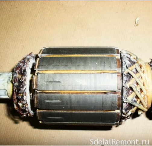
Determination of the integrity of the commutator motor begins with a general visual inspection. In faulty rotor poz.54 traces winding overheat, scratches on the collector, traces of burning on the commutator bars. A short circuit can be determined only at the rotor, in an open circuit which lacks.
To determine the short-circuit(KZ) it is best to use a special device IR-32.
making sure, using said device or instrument improvised, in, that the short-circuiting between the rotor windings, proceed with its dismantling.
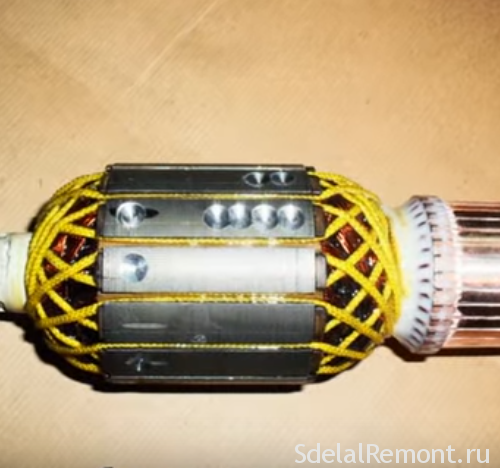
Before dismantling necessarily fix the winding direction. It is very simple. Looking at the rotor end face by the collector, you will see the winding direction. There are two directions of winding: clockwise and anticlockwise. Secure and record, the data you definitely need for self-winding. We Makita rotary hammer rotor winding direction clockwise, right.
disassembly Procedure, repairs, perforator rotor assembly
That sequence rotor repairs a short circuit of windings:
- Pruning end windings.
- Removal collector and coil ends and measuring the diameter of the wires removes.
- Removing and cleaning the isolation grooves with counting the number of turns on the slices.
- Selection of a new collector.
- Installation of a new collector.
- Manufacturing preforms from insulating material.
- Installing cartridges into slots.
- coil yakorya.
- pin layout.
- The process of shrinking.
- reservation shell.
- shell impregnation.
- impregnation collector
- Slotting lamella collector
- balancing
- Trimming and polishing of the rotor.
Now look at everything in order.
Stage I
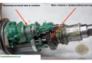
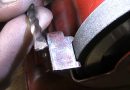
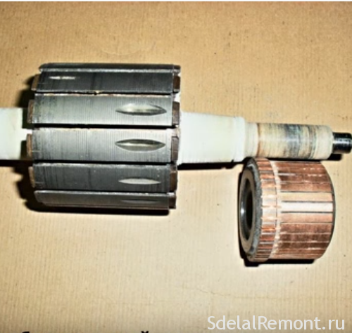
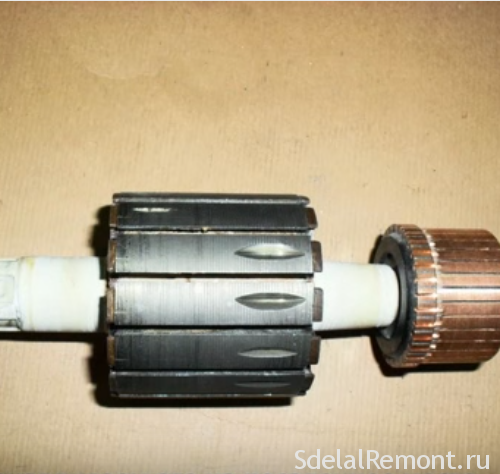
At the first stage it is necessary to remove the anchor collector. The manifold is removed after boring or cutting end windings.
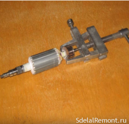
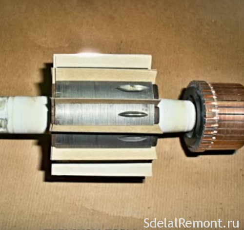
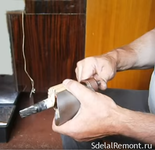
If you are self-repair punch, then sawed the end winding can be with the help of hacksaws for metal. Holding the rotor in the grip through the aluminum pads, Saw circular end winding, as shown in the photo.
Stage II
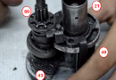
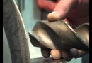
To release the collector, the latter must hold down a key for the gas and turn the slats together with the trimmed end winding, turning a key in different directions.
The rotor thus clamp in a vise through soft metal gasket.
Similarly frontal shooting and a second part, using a pipe wrench.
Always check the rotor fixing force in a vise, constantly pulling clamp.
Stage III
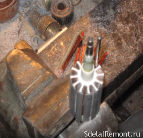
When you remove a collector and sides of the winding, proceed to the removal of residues from the wire grooves, insulation tracks. The best thing to do to use a hammer and chisel aluminum or copper. The insulation must be removed completely, and the surface grooves tipped sandpaper.
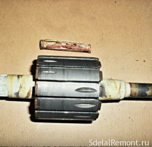
But before, how to remove traces of the winding groove, Try to count the number of turns, arranged in several grooves. With the help of a micrometer, measure the diameter of wire. Be sure to check up, percent as filled grooves conductor rotor. At low levels can be used in the new winding wire of larger diameter.
by the way, insulation can be cleaned, by wrapping a piece of wood with sandpaper desired profile.
Pick a new collector of the desired diameter and design. new collector installation is best done on the wooden bar, the addition of a vertical rotor shaft.
Thrusting collector to the rotor, soft hammer blows through a copper collector nastavku extrude the old place.
It was the turn for the installation of insulation sleeves. For the manufacture of insulation Insulating sleeves Use, Synthoflex, izofleks, varnished cloth. In short, the, that the easiest way to buy.
Now the most difficult and responsible.
As the wind rotor with your hands.
the rotor winding is time-consuming and difficult process and requires patience and perseverance.
Two variants of the winding:
- Self-winding by hand without tools;
- With the use of simple tools.
Variant I
According to a first embodiment, the rotor must be taken in the left hand, and harvested the desired wire diameter and required length with a small margin on the right and the wind, constantly monitoring the number of turns. The rotation of the winding on itself in a clockwise direction.
The procedure for winding simple. Secure the beginning of the wire bearing, thread the slats in the groove and start the winding in the rotor groove opposite the groove slats.
Variant II
you can collect a simple device to facilitate the winding process. It is advisable to collect the device at more than one winding anchors.
Here's the video of simple devices for winding rotor commutator motor.
But we must begin winding data preparation.
The list should include data:
- Rotor Length = 153 mm.
- Length = 45 mm manifold.
- Rotor diameter = 31.5 mm.
- Diameter manifold = 21.5 mm.
- The diameter of the wire.
- Notches = 12.
- Step coil = 5.
- The number of slats on the collector 24 =.
- The direction of the rotor winding coils right =.
- Percentage of wire filling the slots = 89.
These are long, diameter, the number of slots and the number of slats you can get during disassembly of the rotor.
Wire diameter measured with a micrometer, when you pull out a winding of the rotor slots.
All the data you need to collect during the disassembly of the rotor.
The algorithm of the rotor winding
Procedure any rotor winding depends on the number of slots in the rotor, the number of commutator bars. winding direction you set before disassembly and sketched.
The collector, select the reference lamella. This will be the beginning of a winding. Designate the initial point in using lamellae nail.
When dismantling the rotor, we have established, that the rotor grooves 12, while the collector 24 gill.
And we have established, that the winding direction clockwise, when viewed from the collector.
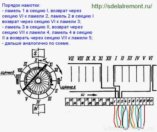
By installing the grooves of the sleeve insulating pressboard or an analogue thereof, soldered to the end of the winding wire slats №1, We start winding.
The wire is placed in the groove 1 in front of, and returns through the sixth slot(1-6), and so on until the desired number of turns with a pitch z = 5. Mid winding soldered to the slats №2 clockwise. In the same section is wound the same number of turns, and the end of the wire is soldered to the slats №3. Removal coil wound.
Start a new reel is made with slats №3, unsolder the middle lamella on №4, wound in the same slots(2-7), and thread fins №5. And so to the state, when the last reel is finished on the slats №1. The cycle has closed.
Solder the ends of the windings to the commutator bars, turn to rotor booking.
Booking Process rotor shell
Reservation of the rotor windings is made for fastening, slat and securing the rotor and its parts during operation at high speed.
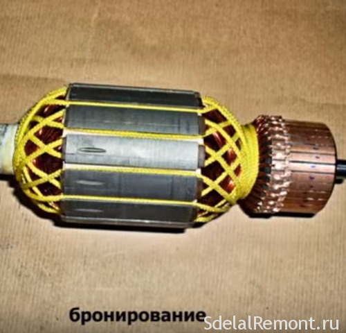
Booking process is called securing the rotor coils by means of a mounting thread.
The impregnation process rotor coils
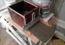
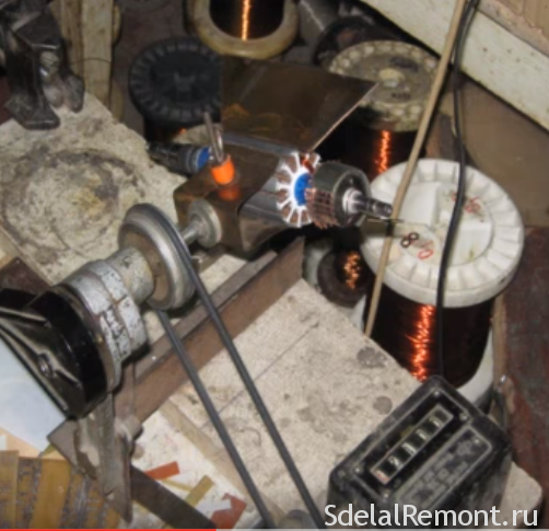
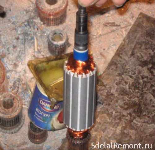
The impregnation of the rotor should be performed with the connection to the AC network. This is done by Latro. But it is better to do this procedure using the transformer, which is supplied to the coil an alternating voltage across LATR.
Photo impregnation Latro
The challenge is, that when an alternating voltage coils wound coils vibrate, heated. And it contributes to a better penetration into the insulation of windings.
The insulating material is recommended to use an epoxy adhesive.

Divorces glue in the warm state in accordance with the instructions. Epoxy adhesive is applied on a heated rotor winding with a wooden blade.
Impregnation perforator rotor Makita 2470 at home
After thorough impregnation allow the rotor to cool. In the process of cooling the impregnation hardens and becomes a solid monolith. You will need to remove it drips.
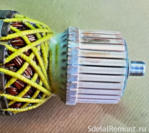
The process of stripping surplus reservoir of impregnation
How would you not carefully and accurately applied impregnation, its particles fall on the commutator bars, flows into the grooves.
In the next stage, and all the necessary grooves and sipes thoroughly cleaned, zapolirovat.
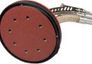
The grooves can be cleaned with a piece of the saw blade, sharpened for cutting Plexiglas. A stripping lamella can produce fine sandpaper, holding the rotor in the electric drill chuck.
First trimmed surface lamellas, then milled grooves collector.
We turn to the balancing of the armature.
The process of balancing armature
It is mandatory for the balance of anchors made vysokooborotisty tool. Makita rotary hammer so is not, but check the balance is not superfluous.
The balanced rotor correctly will significantly increase the time of the bearings, reduce the vibration of the tool, reduce noise rabote.Balansirovku perform at loggerheads, two guide exhibited, in the horizon by the level. Knives are set to the width, allowing the assembled pack on a rotor shaft. The rotor should lie flat.
If disturbed balance of the rotor, it will always be in a position, in which the weight is at the bottom. To compensate for the need to stick to the opposite side of the gasket load coils, so that it does not extend beyond the diameter of the rotor. A can Drill excess metal from overweight.
So, rolling rotor knife, you can it thoroughly otbalansirovat.
Everything! The rotor is ready to install.