Punches are called percussion drilling device, intended for drilling and chiseling holes in high-strength materials.
The punch implemented two ideas: work tool rotates and simultaneously moves longitudinally, creating a shock pulse.
Hammers always work in extreme conditions.
The duration of hammers depends not only on the correct operating conditions, but also the reliability included in the product details.
But no matter how you tried, eventually the guns begin to fail.
To properly repair a punch, you must familiarize yourself with the device.
Overhaul punch Makita 2470 and 2450 his hands can do man, have the skills and metalworker who knows the basics of electrical engineering.
Remember! Compliance with safety regulations and turn off the punch from the network parsing.
Hammers Makita 2450 and 2470 collected almost the same pattern and of the same parts. Repairing them is no different.
For convenience, below is a repair circuit assembly and parts catalog hammers Makita.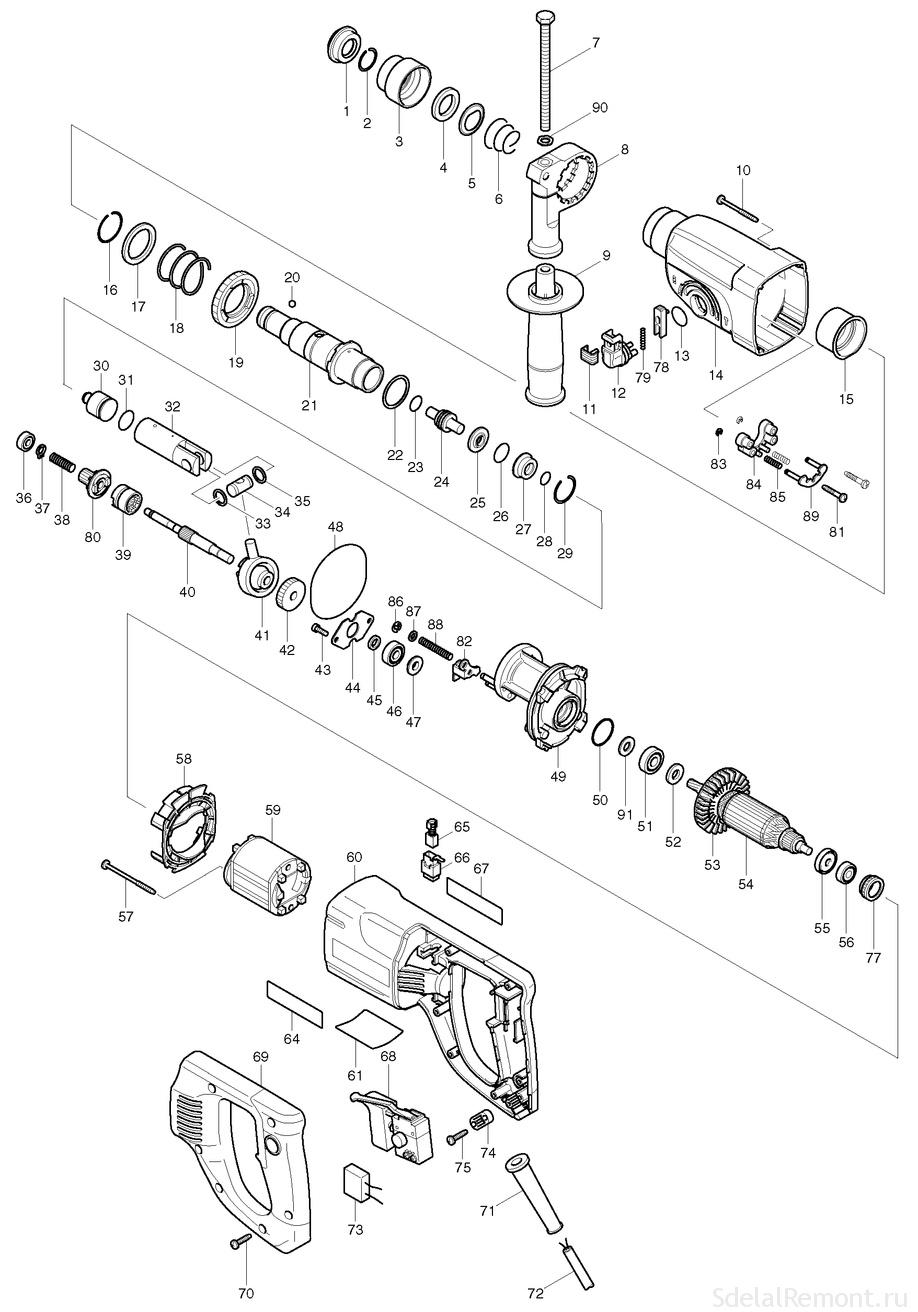
Scheme punch Makita 2450 and 2470 It consists of a mechanical and electrical.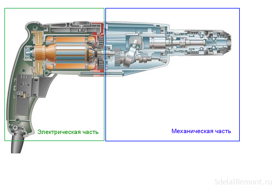
Mechanical part transmits the torque to a drill-borax, creating at the same time progressive movement, creating blow.
Mechanical part consists of a rotary drive and the percussion mechanism.
Schematic diagram of the perforator Makita converts electrical energy into kinetic energy through the rotation of the rotor. The structure of the electrical part includes a motor, button switch with speed control, Reversing switch, connecting wires.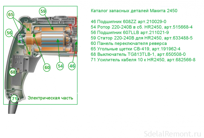 The basic malfunctions perforator makita
Drifters faults are divided into electrical and mechanical.
In this article, we consider all the fault of the electric rotary hammers Makita 2470 and 2450 and how to resolve them:
Electrical faults hammers Makita 2450 and Makita 2470
Electrical faults are shown in the, that when you connect the gun to the power supply, tools not included.
Wiring diagram punch Makita network simple.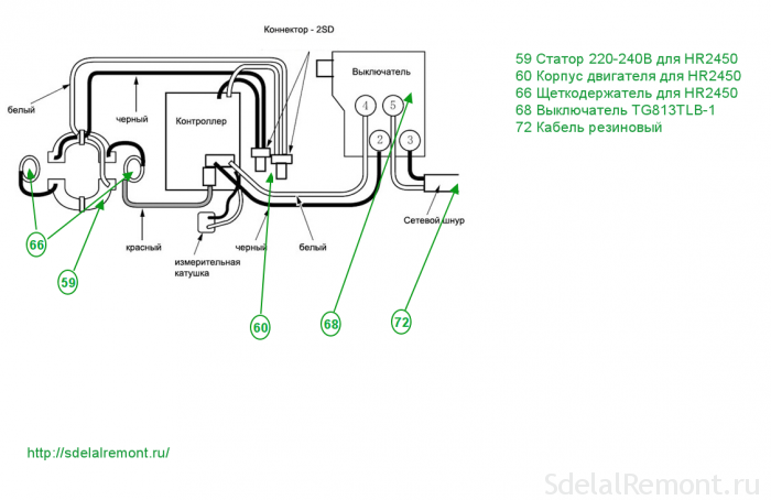
Schematic diagram of the perforator Makita 2450 It is a series connection of the electric motor, Start buttons and wires. Scheme punch Makita 2470 similar to.
After connecting cord poz.72 voltage 220 poz.68 fed through a switch and electrically through brushes on the brush holder poz.66 lamella motor rotor poz.54 , and by reversing the switch contacts poz.60 stator winding poz.59.
The most common fault - lack of contacts in the compounds.
The procedure for determining electrical faults
Determination of the integrity of the electrical part of the perforator Makita. For, to carry out repairs Makita rotary hammer 2450 see или 2470 with their hands should be armed with instruments and tools. You can use any tester, set of screwdrivers, the keys, hammer, wooden nastavka. Good to have a screwdriver with a built-in phase indicator.
It is necessary to take the tester, connect to the ends of the fork and press punch puncher switch. If the tester shows some resistance, the punch supply chain intact.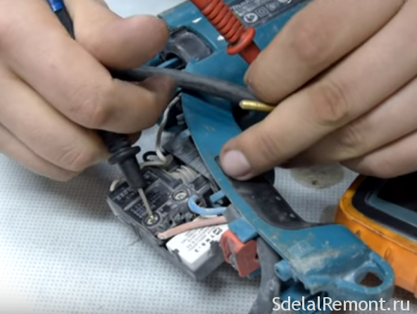
If the tester indicates infinity, then continuity is broken and it is required to remove the rear cover for connecting the control cable and the electro perforator brushes.
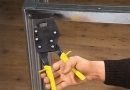
Back cover (usually black) Punch easily removed, you just have to unscrew three screws using a screwdriver or a screwdriver.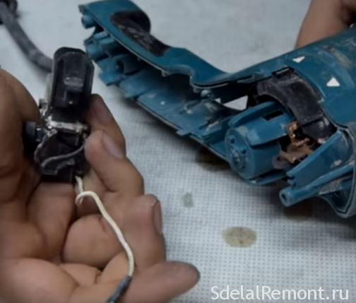
Remove the cover and use a screwdriver to disconnect the wire ends from electrobrushes.
By means of a tester apparatus or improvised, "Arkady," called the people, determine the integrity of the leads and the correct operation of the switch.
A few words about the simple control device called "Arkady". The apparatus consists of an LED light bulb or a flashlight from, penlight batteries and two pieces of wire. The entire electrical circuit of the control device is series connected parts. Connect the battery to one end of the LED or light bulb, the free ends of the LED and the battery, connect the wires. You will have a universal device to verify the integrity of electrical circuits.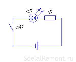
Characteristic malfunctions punch Makita 2450 and 2470
Common fault in the electrical part of the gun Makita 2450 и Spot 2470:
- fracture of the supply cable in place at the entrance to the punch;
- failure TG813TLB-button switch 1, art.650508-0, poz.68.;
- electrical carbon brushes wear SV-419, art.191962-4, poz.65;
- wear reversing switch contacts;
- Wear of the rotor bearing: 609LLU bearing, art.210060-6, poz.51; 607LLU bearing, art.211021-9, poz.56;
- short-circuiting the rotor 220-240 AT, art.515668-8, poz.54;
- failure of the stator winding 220-240 As for HR2450, art.633488-5, poz.59.
In TG813TLB-1 is used as a trigger button switch, art.650508-0; pos. 68.
Replacement brushes made with their full abrasion or poor contact. This fault is detected the strong points of heating installation sites electrobrushes.
Disclaimer inclusion punch can be caused by abrasion of the contacts on the reverse switch.
Eliminated such a failure is very simple.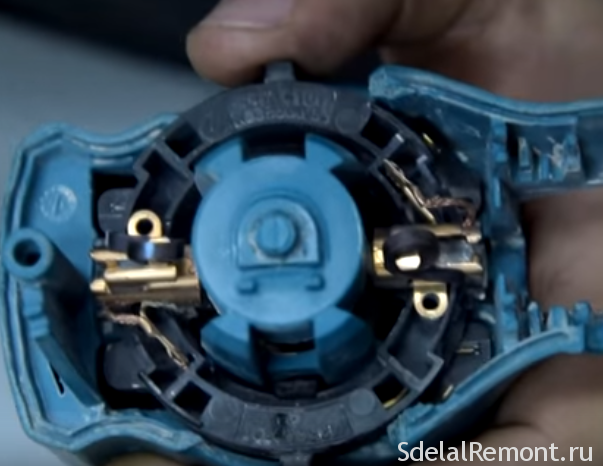
Repair Reverse switch Makita rotary hammer
To repair the reverse switch is necessary to disconnect the rear cover. Carefully disconnect the wires from the button. Inspect the switch.
Further disassembly is to remove the brush holder, pre freeing themselves brush.
After removing the brush holder, you get to the reverse switch contacts.
Determine his condition, replace if necessary contacts.
Another one, frequent electrical fault, poor contact between the stator and lower reversing switch contacts.
Repair of contact between the stator and the reversing switch
To remove the stator, you must disconnect the gearbox housing (black color) from the stator housing (green color).
Remember! The mechanical part of the rotor bearing is pressed special ringlet. When disassembling, do not lose it.
The green body is placed a stator. Looked inside, You see two self-tapping screws 4 × 60, art. 266334-3, poz.57, krepyaschyh stator for housing. Unscrew them, remove the plastic protection for the stator HR2450, art.419201-3, poz.58., release the stator.
When you pull out the stator, You see contacts on the stator and the reversing switch panel.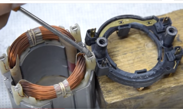
Contacts thoroughly sanded, treated with solvents or alcohol.
Before assembly, bend the contacts so, so they fit into each other. Lubricate contacts a thin layer of petroleum jelly.
Assembling electrical punch in reverse order.